Hardware Requirements for EdgeTX
Conventions used in this document
- SHALL is used to express mandatory requirements (provisions that have to be followed):
- the negative form is SHALL NOT.
- SHOULD is used to express recommendations (provisions that an implementation is expected to follow unless there is a strong reason for not doing so and has to be cleared by the EdgeTX team):
- the negative form is SHOULD NOT.
- MAY is used to express permissible actions (provisions that an implementation is able to follow or not follow):
- the negative form is NEED NOT (in English MAY NOT is ambiguous, so NEED NOT is used instead).
Support of STM32F MCUs
- No new radios based on STM32F2 MCUs will be accepted.
- As of EdgeTX v3.0, no new radios based on STM32F MCUs will be accepted.
Color screen radios
Mandatory hardware features (color)
- MCU: presently only STM32F429BI and STM32F439BI with 2 MB flash are supported. Running at 168 MHz. Support for STM32H7/H7R MCUs is planned from EdgeTX v2.11 onwards, whereas H750 and H7R will be the first supported H7 MCUs.
- SDRAM with minimally 8MB with up to 480x320 pixel screens and minimally 32MB for 800x480 pixel screens.
- SD/microSD card slot or embedded SD NAND (e.g. XTX XTSD04G, minimally 512 MByte). SDIO shall be used to connect the storage device.
- Color display with minimally 480x272 pixels. Presently supported resolutions 480x272, 480x320 and 320x480 pixels. With EdgeTX v3, 800x480 pixel support is planned.
- Either touch-screen or keys for navigation, or both. Presently supported touch-screen controllers: GT911, FT6236, CST836U If no touch-screen is available, minimally, Menu, Enter, Return/Exit, Up, Down, Page and two horizontal trim buttons should be availabe. Up/Down can be substituted with an encoder/roller.
- Display connectivity via RGB565, future support for MIPI-DSI is planned for EdgeTX v3.
- Present display controllers supported: internal STM32F4, ST7796S, HX8357D, ILI9481, ILI9486, ILI9488, NT35310.
- possibility to flash the firmware via USB-DFU (with or without dedicated DFU button)
- the real-time-clock shall be connected to a constantly enabled energy source
- possibility to power down the radio from main microcontroller
- possibility to sample the voltage of the main battery
- Neopixel RGB LEDs shall be connected only on PWM capable pins with DMA support
- Serial-Wire-Debug header shall be available on radios provided to the EdgeTX team. Either pads for 2x5 pin 0.05" header
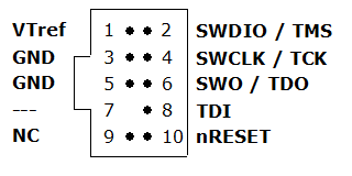
(mandatory are GND, SWDIO, SWCLK and VTref. SWO, TDI and nRESET are optional)
or full-ETM trace header with 2x10 pin 0.05" header:

- USB-C device mode connection
- H7R radios shall support Hi-Speed (480 MBit/s) USB
- For radios with an internal module, lines to put the module into flashing mode to perform pass-through flashing
- Unused GPIO pins shall be connected with a 10k resistor either to GND or VCC. The initial hw revision of a radio shall have them tied to GND, further revision shall use one or multiple of those pins to mark different hw revision of the radio to allow auto detection of the radio version or variant.
- on radios with STM32H750 series MCUs and high-resolution color displays (where the screen resolution is higher than 480x320 pixels), the SDRAM must be connected via 32 bit data bus
- STM32H7, STM32H7R, STM32H7S and STM32H5 MCUs have a modernised UART/UASART hardware
- no inverters SHALL be connected to the UART/USART pins, the MCU can handle polarity inversion in HW, without external help
- the S.PORT pin of the module bay SHALL be connected directly to the MCU UART/USART TX pin, NO inverter or direction switch logic is needed, add a 10kOhm pull up resistor. The MCU can handle half-duplex in hardware, without external help
Hardware design guidelines
- all high speed interfaces like Quad/Octo/Hexa SPI, SDRAM, USB and SDIO shall be length / time of flight equalised
- relative timing constraints, e.g. for different SDRAM wires, shall be respected
- STM32H7 CPUs shall be used with Quad or Octo SPI flash that supports DDR and at least 100 MHz of DDR SPI clock speed
- for connecting the Quad/Octp SPI flash and RAM the pins used on the evaluation boards shall be used
- For H7R, STM32H7S78-DK
- For H7, STM32H750B-DK
- STM32H7R MCUs may be used with Hexa-SPI PSRAM, one possible type is the IC used on the evaluation board.
- the STM32H7RS series support 480 MBit/s USB on USB2 and 12 MBit/s USB on USB1. The MCU internal bootrom supports DFU mode only on USB1, so a USB switch, like the FSUSB42 by Onsmi, should be added, with the default set to USB 1, to be able to use DFU mode and 480 MBit/s USB
- on radios with STM32H750 series MCUs, it is advised to connect the SDRAM to the MCU via 32 bit bus (minimally 16-bit bus is needed, 32-bit bus provides a performance benefit)
- all connectors that are accessible without opening the radio (antenna, module bay, UARTs, SD card slot, ...) need to have an ESD protection, to be compliant to EU CE regulations. The relevant standard is IEC 61000-4-2, the test level should be level 4. You can find an overview on ESD protection methods there: https://www.st.com/resource/en/application_note/an5612-esd-protection-of-stm32-mcus-and-mpus-stmicroelectronics.pdf
Optional (color)
- Display backlight shall be controllable via PWM - connection to hw-PWM capable pin on the MCU
- Gimbals with either analog, PWM (e.g. TLE4998P3), SPI ADC (e.g. ADS7952) or UART communication
- Switches as digital or analog inputs
- haptic vibrator, via binary or PWM output
- support for additional key navigation input. Supported keys: Enter, Return, Page>, Page<, Up/Down, System, Model, Tele.
- support for encoder/roller user input
- Audio output via STM32 integrated DAC or via SPI codec (e.g. VS1053B is already supported)
- Explicit audio volume control, e.g. via I2C, SPI or further DAC output
- Explicit audio mute pin
- in case of integrated charging circuitry/circuitries, feedback to main MCU about charging status of each charger
- for external RF module bay support: either JR-micro or JR-nano bay
- If trainer socket present: in/out connected to hw-PWM capable pins
- GPIO extenders with I2C or SPI bus connectivity can be used for digital I/O. In case GPIO extenders are used as inputs, the interrupt output of the GPIO extender shall be connected to an input interrupt capable pin of the MCU. The interrupt lines of multiple GPIO extenders may be logically connected to the same MCU input line.
- SPI flash
- I2C EEPROM
- Bluetooth module via UART
- IMU (e.g. LSM6DS33)
- I2C port expander
- if port expanders are used for inputs, the interrupt output pin(s) of the port expander(s) shall be connected to an interrupt capable input pin of the MCU
- SpaceMouse module
Black-and-white radios
Mandatory hardware features (B/W)
- MCU: As of EdgeTX 2.10, STM32F4 with minimally 1 MB flash running at 168 MHz. From EdgeTX v2.11 onwards, STM32H562/563 will also be supported. New STM32F based designs will not be accepted as of EdgeTX v3.0.
- Support for STM32H562/563 will be available from EdgeTX v3 or v2.11
- SD/microSD card slot or embedded SD NAND (e.g. XTX XTSD04G, minimally 512 MByte)
- Starting with STM32H5 all new radios shall use SDIO to connect the storage
- Monochrome display with either 128x64 pixels or 212x64 pixels.
- possibility to flash the firmware via USB-DFU (with or without dedicated DFU button)
- constantly enabled energy source for the real-time-clock
- Keys to navigate the menus. Minimally, Menu, Enter, Return/Exit, Up, Down, Page and two horizontal trim buttons should be available. Up/Down can be substituted with an encoder/roller.
- possibility to power down the radio from main microcontroller
- possibility to sample the voltage of the main battery
- Neopixel RGB LEDs only on PWM capable pins with DMA support
- Serial-Wire-Debug header. Either pads for 2x5 pin 0.05" header
(mandatory are GND, SWDIO, SWCLK and VTref. SWO, TDI and nRESET are optional)
or full-ETM trace header with 2x10 pin 0.05" header:
- USB-C device mode connection (minimally for new radios)
- For radios with an internal module, lines to put the module into flashing mode to perform pass-through flashing
- Unused GPIO pins shall be connected with a 10k resistor either to GND or VCC. The initial hw revision of a radio shall have them tied to GND, further revision shall use one or multiple of those pins to mark different hw revision of the radio to allow auto detection of the radio version or variant.
- STM32H7, STM32H7R, STM32H7S and STM32H5 MCUs have a modernised UART/UASART hardware
- no inverters SHALL be connected to the UART/USART pins, the MCU can handle polarity inversion in HW, without external help
- the S.PORT pin of the module bay SHALL be connected directly to the MCU UART/USART TX pin, NO inverter or direction switch logic is needed, add a 10kOhm pull up resistor. The MCU can handle half-duplex in hardware, without external help
hardware design guidlines
- all high speed interfaces like Quad/Octo/Hexa SPI, SDRAM, USB and SDIO shall be length / time of flight equalised
- possible pin assignments can be found in the documentation of the evaluation board: NUCLEO-H563ZI
- all connectors that are accessible without opening the radio (antenna, module bay, UARTs, SD card slot, ...) need to have an ESD protection, to be comliant to EU CE regulations. The relevant standard is IEC 61000-4-2, the test level should be level 4. You can find an overview on ESD protection methods there: https://www.st.com/resource/en/application_note/an5612-esd-protection-of-stm32-mcus-and-mpus-stmicroelectronics.pdf
Optional (B/W)
- Display backlight control via PWM - connection to hw-PWM capable pin on the MCU
- Gimbals with either analog, PWM (e.g. TLE4998P3), SPI ADC (e.g. ADS7952) or UART communication
- Switches as digital or analog inputs
- haptic vibrator, via binary or PWM output
- support for additional key navigation input, via keys: Enter, Return, Page>, Page<, Up/Down, System, Model, Tele.
- support for encoder/roller user input
- Audio output via STM32 integrated DAC
- Explicit audio volume control, e.g. via I2C, SPI or further DAC output
- Explicit audio mute pin
- in case of integrated charging circuitry/circuitries, feedback to main MCU about charging status of each charger
- for external RF module bay support: either JR-micro or JR-nano bay
- If trainer socket present: in/out shall be connected to hw-PWM capable pins
- GPIO extenders with I2C or SPI bus connectivity can be used for digital I/O. In case GPIO extenders are used as inputs, the interrupt output of the GPIO extender shall be connected to an input interrupt capable pin of the MCU. The interrupt lines of multiple GPIO extenders may be logically connected to the same MCU input line.
- SPI flash
- I2C EEPROM
- Bluetooth module via UART
- IMU (e.g. LSM6DS33)
- I2C port expander
- if port expanders are used for inputs, the interrupt output pin(s) of the port expander(s) shall be connected to an interrupt capable input pin of the MCU
General Considerations
- When the radio is equipped with flight mode buttons (6POS / six position switch), they should be connected in a way that they can be used individually (as 'customizable switches' in EdgeTX). In order to save MCU IO pins, this may be done using a single analog input and resistor ladder, or an I2C expander. These switches shall have visual feedback LEDs that can be controlled by the MCU. To save MCU IO pins, this may also be done using an I2C expander, or WS2812 (aka Neopixel) single serial line LEDs.
- Since the H7R and H5 CPUs support USB-C power delivery, the charging circuit may be designed with this in mind.
- In order for the radio with a proprietary (meaning non open-source) internal RF technology to be included in the officially supported radios list, the EdgeTX development team needs to be provided with detailed documentation regarding the API of such internal RF module. In addition, any officially supported radio with a proprietary internal RF module, needs to be equipped in addition with an external RF module bay that is able to accept open-source RF technology (such as Multi-Protocol-Module and ExpressLRS).